Sprockets are critical components in power transmission systems, facilitating the efficient transfer of rotary motion and torque via a chain. Their performance, durability, and reliability are determined by manufacturing processes, bore sizes, and hub designs. This article provides a detailed overview of these key aspects.
1. Manufacturing Processes of Sprockets
The manufacturing of sprockets involves a series of precise processes tailored to material specifications, performance requirements, and production volume.
Key Processes:
- Blank Preparation: Blanks are cut from bar stock, plate, or tube using sawing, flame/plasma cutting, or turning.
- Forming (Optional): For enhanced mechanical properties, blanks may be forged to refine grain structure. Large or complex sprockets for low-speed applications might be cast for cost-effectiveness.
- Heat Treatment: This is crucial for performance.
- Preparatory: Normalizing or annealing relieves stresses from prior operations and softens the material for easier machining.
- Final: Quenching and tempering (hardening and drawing) is common to achieve high surface hardness and core toughness. Induction hardening selectively hardens the tooth surface for wear resistance with minimal distortion. Carburizing or nitriding enriches the surface with carbon or nitrogen for extreme wear and fatigue resistance.
- Machining: This shapes the final product.
- Turning: Rough and finish turning operations create the outer diameter, bore, and side faces, ensuring precise reference surfaces.
- Tooth Generation: The critical step of forming the teeth.
- Gear hobbing is the most efficient and common method for high-volume production.
- Gear shaping is used for sprockets with tight spacing or internal teeth.
- Gear milling offers flexibility for low-volume production or large sprockets.
- Other Operations: Drilling, tapping, and keyway broaching add necessary features.
- Finishing: Processes like deburring, topping (chamfering tooth edges), and surface treatments (blackening, galvanizing, phosphating) improve safety, longevity, and corrosion resistance.
Production Workflows:
- Low-Volume: Focuses on flexibility: Blank → Turn → Mill Teeth → Drill/Broach → Heat Treat.
- High-Volume: Focuses on efficiency and consistency: Forge → Rough Turn → Quench & Temper → Finish Turn → Hob Teeth → Drill/Broach → Induction Harden → Finish.
Special Processes:
- Powder Metallurgy (P/M): Ideal for mass-producing small, complex-shaped sprockets with minimal material waste.
- Wire EDM: Used for cutting precise teeth in pre-hardened materials or for creating unique tooth profiles.
- Plastic Coatings: Applied for corrosion resistance, noise reduction, or operation in clean environments.
2. Sprocket Bore Sizes
The bore size is not arbitrary; it is a functional dimension determined by the shaft it mounts onto.
Governing Principle: The bore diameter is designed to match the calculated shaft diameter with a specific tolerance (e.g., H7) for a secure press or slide fit.
Common Size Ranges:
- The most typical bore sizes fall within the Ø12 mm to Ø100 mm range, covering most industrial and agricultural machinery.
- Smaller bores (< Ø10 mm) are found in precision instruments.
- Larger bores (up to Ø200+ mm) are used in heavy-duty mining and metallurgical equipment.
Standardization & Keyways: While bore sizes themselves are customizable, they are often designed around preferred number series (e.g., 20, 25, 30, 40, 50 mm) to simplify manufacturing and inventory. The associated keyway dimensions are fully standardized (e.g., ISO 773, GB/T 1095, ANSI B17.1) based on the bore diameter to ensure compatibility with standard keys.
How to Determine the Correct Bore:
- Design Calculation: The shaft diameter is calculated based on transmitted torque and power. The sprocket bore is then this diameter plus the required fit tolerance.
- Measurement: For replacement, directly measure the existing shaft diameter with calipers.
- Supplier Consultation: Manufacturers offer sprockets with standard bore sizes or can machine custom bores to customer specifications.
3. Hub Designs: The Purpose of the Hub
A sprocket can be a simple plate (plain bore) or have a protrusion known as a hub. This design choice balances cost, strength, and installation needs.
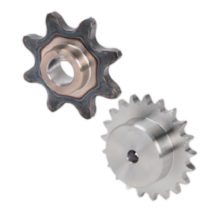
Plain Bore Sprockets (Without Hub):
- Advantages: Low cost, lightweight, and compact (saves axial space).
- Disadvantages: Lower strength and rigidity, prone to bending under heavy load, no dedicated surface for secure clamping.
- Applications: Ideal for light-duty, low-speed applications where cost and space are primary concerns.
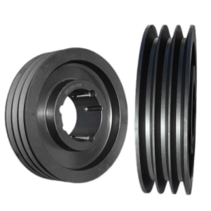
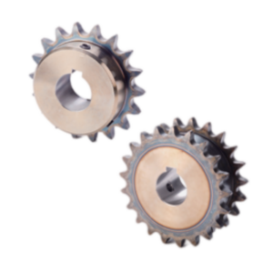
Hubbed Sprockets (With Hub):
- Advantages: Superior strength and rigidity to handle heavy loads and shock, provides a robust surface for set screws or clamps without distorting the tooth profile, allows for larger bore sizes, better heat dissipation.
- Disadvantages: Higher cost, increased weight, and greater width (may cause interference in tight spaces).
- Applications: Essential for heavy-duty, high-speed, high-impact applications (e.g., mining, forestry, heavy conveyors).
Hub Variations: Hubs can be single-sided or double-sided. A double hub offers the greatest rigidity and provides a surface for clamping mechanisms on both sides, further securing the sprocket to the shaft.
4. Are Hub Dimensions Standardized?
Hub dimensions are not governed by a global ISO or ANSI standard. However, they are far from arbitrary.
- Industry Conventions: Hub sizes are based on engineering principles and industry practice. Hub diameter (
D_hub) is typically 1.5 to 2.0 times the bore diameter (d) and is often related to the sprocket’s pitch diameter. - Manufacturer Standards: Major manufacturers develop their own dimensional specifications for each sprocket type and size. These are published in product catalogs and are the de facto standard for selection and interchangeability within that brand.
- Standardized Features: While the hub’s overall size is custom, the features on it are standardized:
- The keyway must conform to keyway standards.
- Set screw threads (e.g., M6, M8) and their positioning follow standard practices.