1. Overview of Couplings
A coupling is a mechanical device used to connect two shafts or a shaft to a rotating component in a power transmission system. Its primary functions include transmitting torque and motion, compensating for misalignment (axial, radial, and angular), and providing vibration damping and overload protection. Couplings can be broadly classified into rigid couplings and flexible couplings.
2. Common Types of Couplings and Their Characteristics
2.1 Rigid Couplings
(1) Flange Coupling
- Structure: Consists of two flanged hubs bolted together.
- Advantages: Simple design, high torque capacity, excellent alignment.
- Disadvantages: No misalignment compensation, requires precise installation.
- Applications: Low-speed, heavy-duty applications with good shaft alignment.
(2) Sleeve Coupling
- Structure: A cylindrical sleeve connects two shafts using keys or pins.
- Advantages: Compact design, simplest construction.
- Disadvantages: Difficult to assemble/disassemble, requires axial shaft movement.
- Applications: Low-power, light-duty, short-shaft connections.
2.2 Flexible Couplings
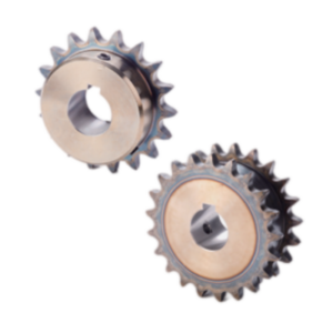
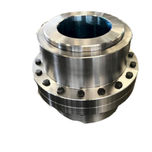
(1) Gear Coupling
- Structure: Composed of two hubs with external gear teeth and a sleeve with internal teeth.
- Advantages: High torque capacity, compensates for large misalignment.
- Disadvantages: Requires lubrication, high manufacturing precision.
- Applications: Heavy machinery, metallurgy, mining.
(2) Oldham Coupling
- Structure: Two hubs with slots and a central floating disc.
- Advantages: Compact, compensates for parallel misalignment.
- Disadvantages: Wear-prone, requires lubrication.
- Applications: Low-speed (<300 RPM), high-rigidity shafts.
(3) Universal Joint (U-Joint)
- Structure: Consists of a cross-shaped spider and two yokes.
- Advantages: Allows large angular misalignment (15°–45°).
- Disadvantages: Speed fluctuations, often used in pairs.
- Applications: Automotive driveshafts, rolling mills.
(4) Jaw Coupling (Spider Coupling)
- Structure: Uses an elastomeric spider insert between two metal hubs.
- Advantages: Damping, electrical insulation, maintenance-free.
- Disadvantages: Limited load capacity.
- Applications: Pumps, fans, light-to-medium power transmission.
(5) Elastomeric Pin Coupling
- Structure: Nylon or rubber pins connect two hubs.
- Advantages: Simple, cost-effective, shock absorption.
- Disadvantages: Limited temperature range (-20°C to 70°C).
- Applications: Frequent start-stop machinery.
(6) Diaphragm Coupling
- Structure: Uses thin metal diaphragms to transmit torque.
- Advantages: Zero backlash, maintenance-free, high-speed capability.
- Disadvantages: Limited angular misalignment compensation.
- Applications: Turbomachinery, precision drives.
(7) Tire Coupling
- Structure: Rubber tire element connects two hubs.
- Advantages: Excellent vibration damping, high misalignment tolerance.
- Disadvantages: Bulky, susceptible to aging.
- Applications: High-shock applications.
(8) Bellows Coupling
- Structure: Uses a flexible metal bellows for torque transmission.
- Advantages: Zero backlash, high torsional stiffness.
- Disadvantages: Lower torque capacity.
- Applications: Servo systems, precision instruments.
3. Performance Comparison
| Coupling Type | Max Speed (RPM) | Torque Range (N·m) | Axial Comp. (mm) | Radial Comp. (mm) | Angular Comp. (°) | Damping | Maintenance |
|---|---|---|---|---|---|---|---|
| Flange Coupling | 3,000–5,000 | 100–10⁶ | None | None | None | None | Low |
| Gear Coupling | 1,000–4,000 | 10²–10⁶ | 3–15 | 0.5–6 | 0.5–1.5 | Moderate | High |
| Jaw Coupling | 5,000–20,000 | 0.1–20,000 | 0.5–5 | 0.2–2 | 0.5–3 | Good | None |
| Diaphragm Coupling | 10,000–50,000 | 1–50,000 | 0.2–2 | 0.1–1 | 0.1–1 | Moderate | None |
| Universal Joint | 1,000–3,000 | 10–10⁵ | 5–50 | 5–20 | 15–45 | None | Medium |
| Tire Coupling | 1,000–4,000 | 10–50,000 | 5–20 | 2–10 | 2–10 | Excellent | Medium |
4. Selection Criteria
- Torque Transmission: Calculate working torque, including start-up and overload factors.
- Speed Range: Must not exceed coupling’s maximum rated speed.
- Misalignment Tolerance: Choose based on expected axial, radial, and angular deviations.
- Environmental Conditions: Consider temperature, humidity, and corrosive elements.
- Space Constraints: Account for radial and axial dimensions.
- Maintenance Requirements: Decide between maintenance-free or lubricated types.
- Cost Considerations: Balance initial cost with service life.
5. Future Trends
- Advanced Elastomers: Development of high-temperature, corrosion-resistant materials.
- Smart Monitoring: Integration of sensors for condition-based maintenance.
- Lightweight Designs: Use of high-strength alloys and optimized geometry.
- Modular Systems: Improved interchangeability and adaptability.
- Precision Couplings: Meeting demands of high-accuracy servo systems.