In heavy-duty industrial machinery, transmitting high torque between two rotating shafts requires more than a strong mechanical connection. Thermal expansion, shaft deflection, and small installation errors can introduce misalignment during operation.
A crowned gear coupling, also known as a drum gear coupling or curved-tooth gear coupling, uses meshing steel gear teeth to transmit torque while accommodating limited shaft misalignment.
This guide explains how a double-engagement crowned gear coupling works, how its components fit together, why the external teeth are crowned, and what engineers should consider when selecting one.
What Is a Crowned Gear Coupling?
A crowned gear coupling is a mechanically flexible shaft coupling that transfers torque through mating external and internal gear teeth.
Unlike a rigid flange coupling, it allows limited relative angular movement between connected components. The external gear teeth are slightly crowned across their face width to accommodate angular displacement and help reduce the risk of concentrated contact at the tooth edges.
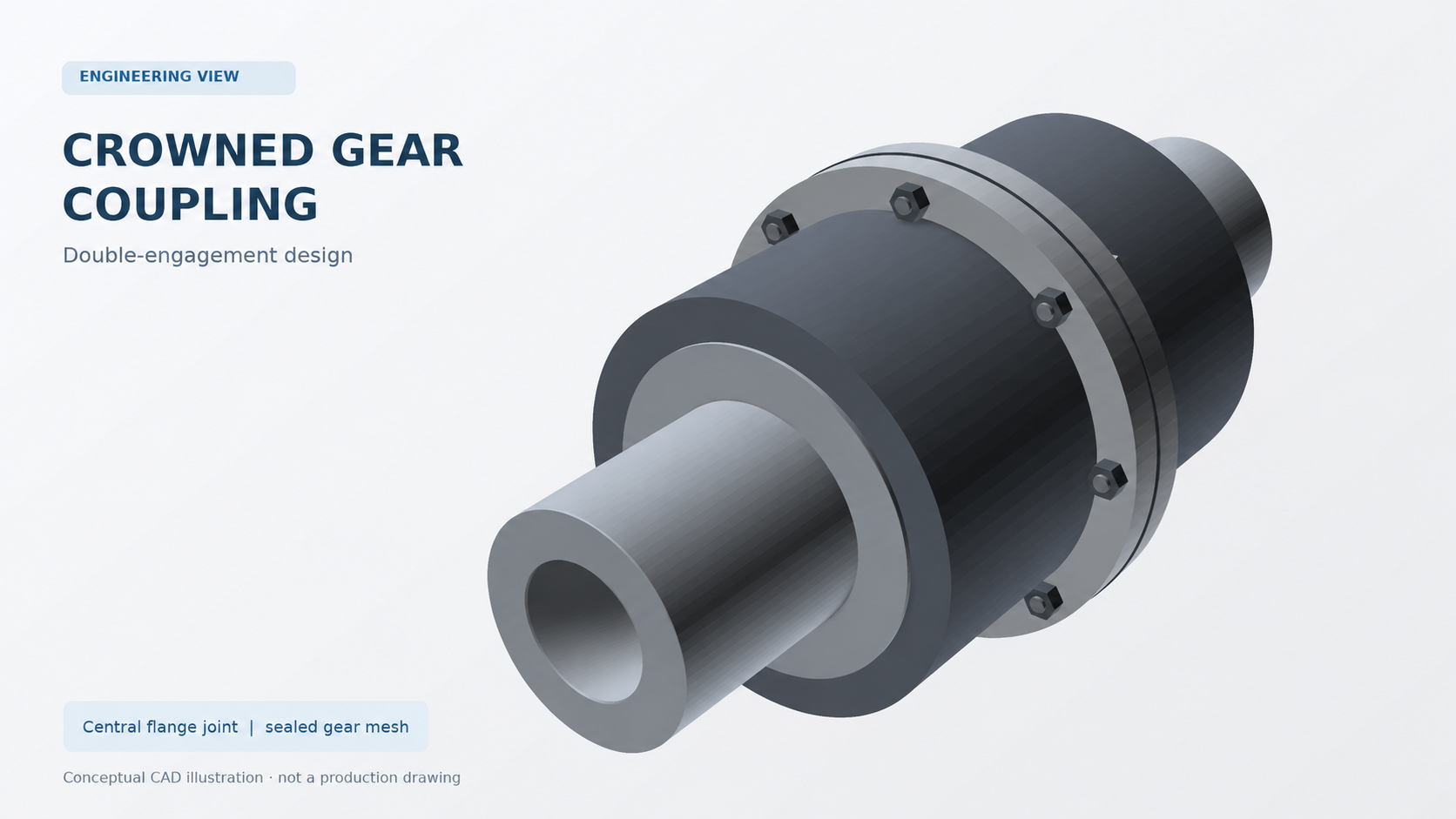
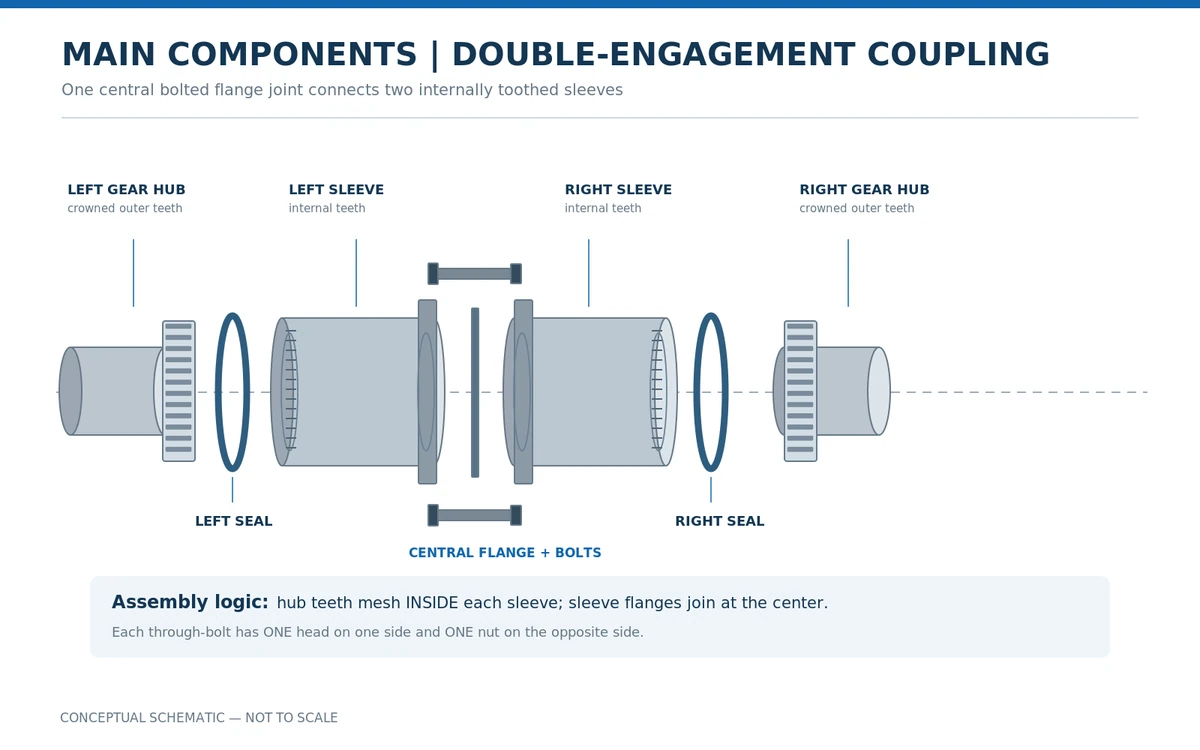
The common double-engagement arrangement consists of two external gear hubs, two internally toothed sleeves, a central bolted flange connection, and sealing components.
These features make crowned gear couplings suitable for many industrial drives requiring high torque transmission within a relatively compact assembly.
However, misalignment capacity is limited and design-dependent. A gear coupling should never be treated as a substitute for proper shaft alignment.
Main Components of a Double-Engagement Gear Coupling
Understanding the internal structure is important when specifying replacement parts, investigating wear, or evaluating a coupling for an OEM application.
External Gear Hubs
Each hub is mounted to its corresponding shaft and has external gear teeth that engage with an internally toothed sleeve.
The characteristic feature is the crowned tooth geometry. Instead of maintaining a constant tooth thickness across the entire face width, the tooth surface is modified to provide relief toward the ends.
Depending on the design, the hubs may use keyed bores, interference fits, or other specified shaft connections.
Internally Toothed Sleeves
Each sleeve contains internal teeth that mesh with one external gear hub.
The two sleeves form separate gear engagements and are joined at the center through their flanges.
This arrangement provides a torque path between the driving and driven shafts while allowing limited relative movement at the gear meshes.
Central Flanges and Bolts
The sleeve flanges are connected by bolts, creating the mechanical connection between the two sides of the coupling.
Bolt size, grade, tightening method, and preload must follow the selected coupling design. Incorrect assembly can compromise joint integrity.
Seals and Lubrication Space
The gear engagements are normally enclosed, with seals helping retain lubricant and reduce contamination.
Most conventional enclosed steel gear couplings depend on an appropriate lubricant to protect the mating tooth surfaces during operation.
Seal condition and lubrication are therefore important maintenance considerations, particularly in dusty industrial environments.
How Does a Crowned Gear Coupling Transmit Torque?
A double-engagement coupling transmits torque through a continuous mechanical path:
- Driving shaft to the first hub: Torque enters the coupling through the hub’s shaft connection.
- First hub to the first sleeve: The crowned external teeth mesh with the internal sleeve teeth.
- Across the central flange joint: The bolted flanges transfer torque between the two sleeves.
- Second sleeve to the driven shaft: Torque passes through the second gear engagement and hub to the driven shaft.
The two gear engagements permit limited relative movement while maintaining torque transmission.
Because the coupling relies on metallic gear contact, it is relatively torsionally rigid compared with many elastomeric couplings. It does not inherently provide the same degree of vibration damping as a rubber-element or jaw-type coupling.
This distinction matters when an application requires both torque transmission and substantial torsional vibration isolation.
Why Are Crowned Gear Teeth Important?
The tooth geometry is what distinguishes a crowned gear coupling from a comparable arrangement with straight, unmodified tooth faces.
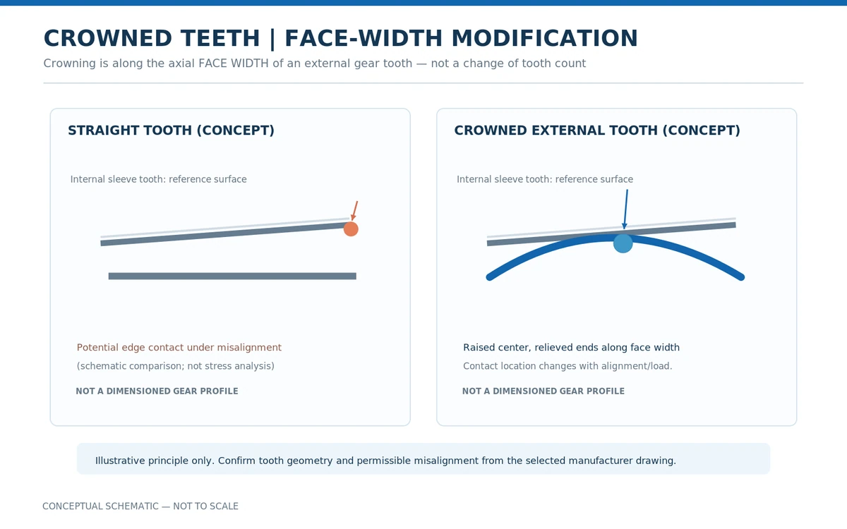
In a crowned design, the external tooth is modified along its axial face width. This should not be confused with changing the tooth count or replacing the basic involute tooth form.
Straight Teeth and Edge Contact
When mating gear teeth experience angular displacement, the contact pattern can shift toward one end of the tooth face.
With insufficient tooth relief, this may create unfavorable edge loading and localized contact stress.
Repeated operation under these conditions can contribute to accelerated wear or tooth damage.
Crowned Teeth and Contact Distribution
The crowned profile introduces relief toward the ends of the tooth face.
Under appropriate operating conditions, this geometry can reduce the tendency for severe edge contact as the hub moves relative to the sleeve.
However, crowning does not guarantee uniform contact in every condition.
The actual contact pattern depends on tooth geometry, applied torque, alignment, manufacturing accuracy, and lubrication.
Engineering note: The illustration explains the principle only. Exact crowning geometry and permissible angular movement must be established using the selected manufacturer’s drawings and technical data.
What Types of Shaft Misalignment Can a Gear Coupling Accommodate?
Industrial machinery rarely maintains perfect shaft alignment under every operating condition.
Equipment foundations, thermal growth, bearing loads, and shaft deflection can alter the relative positions of connected shafts.
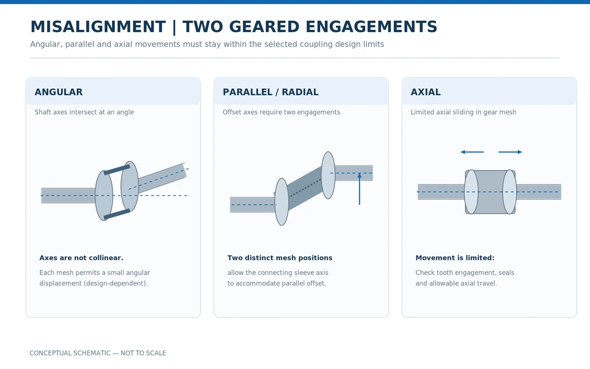
A properly selected double-engagement crowned gear coupling can accommodate limited angular, parallel, and axial displacement.
1. Angular Misalignment
Angular misalignment occurs when the rotational axes of the connected shafts are not parallel and intersect at an angle.
At each gear engagement, the crowned tooth geometry permits limited relative angular displacement between the hub and sleeve.
The allowable angular displacement depends on the coupling’s dimensions, gear geometry, and operating conditions.
Excessive angular misalignment can increase sliding motion, change the tooth contact pattern, and accelerate wear.
2. Parallel or Radial Misalignment
Parallel misalignment occurs when the two shaft axes remain approximately parallel but are laterally offset.
A double-engagement gear coupling accommodates this condition through angular displacement at two separate gear mesh positions.
The connecting sleeve assembly can consequently operate at an angle relative to the shaft axes.
The allowable parallel offset depends partly on the distance between engagement positions and the permissible angular displacement of the selected design.
A single-engagement arrangement does not provide the same parallel-offset capability.
3. Axial Displacement
Axial displacement occurs when the relative positions of connected shafts change along their rotational axes.
Some gear coupling designs accommodate limited axial movement through relative sliding at the gear engagement.
Nevertheless, the available movement is restricted by the coupling’s geometry, effective tooth engagement, seals, and axial clearances.
Engineers must confirm the allowable axial travel rather than assuming unrestricted movement.
Why Misalignment Limits Matter
Angular, parallel, and axial displacement limits should not be considered independently when several types of misalignment occur simultaneously.
Combined displacement may require lower individual limits.
For reliable operation, alignment should be checked during installation and against expected changes under operating conditions.
A coupling’s ability to accommodate misalignment does not eliminate the need to align the connected equipment accurately.
Typical Applications of Crowned Gear Couplings
Crowned gear couplings are frequently considered for industrial power transmission systems where compact construction and substantial torque capacity are important.
Mining and Mineral Processing
Heavy-duty mining equipment may experience significant transmitted loads, contamination, and prolonged operating cycles.
Typical applications include crushers, ball mills, material-handling conveyors, and certain hoisting drives.
Coupling selection must account for shock loading, shaft alignment, lubrication access, and maintenance conditions.
Steel Mills and Metallurgical Equipment
Rolling mills, straightening equipment, and other metallurgical drives can impose demanding torque and duty-cycle requirements.
Gear couplings are used in suitable configurations to connect drivetrain components in these applications.
Thermal growth and changing operating loads make shaft alignment and tooth lubrication particularly important.
Cranes and Hoisting Systems
Crane travel mechanisms, hoists, and other lifting equipment may use suitable gear coupling configurations.
Some designs incorporate brake wheels or additional components, but these are distinct arrangements requiring their own rated drawings and selection criteria.
Power Generation and Industrial Processing
Large pumps, fans, material-processing equipment, and other rotating industrial machines may use gear couplings where their torque capacity and mechanical characteristics match the duty.
High operating speed, balance requirements, shaft movement, and lubrication arrangements must all be evaluated before specifying a coupling.
When Is a Crowned Gear Coupling Not the Best Choice?
Despite its advantages, a crowned gear coupling is not appropriate for every drive system.
It may be a less suitable choice when the application requires significant torsional damping, operation with little or no lubrication maintenance, or shaft movement beyond the coupling’s specified limits.
Certain high-speed applications also require special attention to dynamic balance, lubrication, and manufacturer speed ratings.
In applications where vibration isolation is a primary requirement, an elastomeric coupling may be more appropriate. For a broader comparison, read our Jaw Couplings vs. Gear Couplings guide.
How to Select a Crowned Gear Coupling for Your Equipment
For an OEM project or replacement application, selecting a coupling by outside diameter or model name alone is not sufficient.
The following information helps establish a suitable specification:
| Selection parameter | What to confirm |
|---|---|
| Transmitted torque | Continuous, peak, and starting torque |
| Operating speed | Normal and maximum rotational speed |
| Shaft dimensions | Bore diameters, keyways, fits, and shaft-end dimensions |
| Shaft arrangement | Distance between shaft ends and coupling installation space |
| Misalignment | Expected angular, parallel, and axial displacement |
| Operating conditions | Shock loads, temperature, contaminants, and duty cycle |
| Material and treatment | Required steel grade, heat treatment, and tooth hardness |
| Lubrication | Lubricant type, seals, maintenance access, and operating requirements |
For replacement couplings, the original manufacturer’s drawing or an accurately measured sample should also be reviewed.
Model families such as GICL and GIICL use different construction and dimensional specifications. A similar-looking designation should not be treated as proof of interchangeability.
Where an intermediate shaft or a brake-wheel arrangement is required, the full assembly design must be considered rather than selecting the gear engagement alone.
Installation and Maintenance Considerations
Correct installation is essential to achieving reliable coupling operation.
Before commissioning, installers should verify shaft alignment, mounting dimensions, hub retention, flange fasteners, and lubricant requirements according to the applicable instructions.
During service, inspection may include checking for lubricant leakage, damaged seals, loose fasteners, abnormal vibration, and evidence of tooth wear.
A noisy coupling does not necessarily indicate a defective tooth profile. Excessive misalignment, lubrication problems, damaged components, or issues elsewhere in the drivetrain may produce similar symptoms.
Inspection of internal components should only be performed after the machine has been safely stopped and isolated.
Frequently Asked Questions
Is a crowned gear coupling a flexible coupling?
Yes. It is mechanically flexible because its gear engagements permit limited relative movement between connected shafts. However, it is not equivalent to an elastomeric coupling in terms of torsional flexibility or damping.
What is the difference between a crowned gear coupling and a straight-tooth gear coupling?
The principal difference is the modification of the external tooth across its face width. Crowned teeth provide end relief that helps accommodate angular displacement and reduce undesirable edge contact within the coupling’s design limits.
Can a double-engagement gear coupling handle parallel misalignment?
Yes, within its rated limits. The two separate gear engagements allow angular movement at two positions, enabling the connecting assembly to accommodate limited parallel shaft offset.
Do crowned gear couplings require lubrication?
Most conventional enclosed steel gear couplings require lubrication at the meshing teeth. The correct lubricant, quantity, and maintenance interval depend on the specific coupling design and operating conditions.
Can an existing GIICL coupling be replaced with another manufacturer’s model?
Potentially, but the model designation alone is not sufficient. The replacement must be checked for torque capacity, speed rating, bore dimensions, shaft spacing, mounting details, and other relevant specifications.
Conclusion
A crowned gear coupling provides a compact mechanical solution for transmitting substantial torque while accommodating limited shaft misalignment.
Its performance depends on the interaction between the crowned external teeth, internally toothed sleeves, central flange connection, lubrication system, and installation alignment.
For OEM equipment manufacturers and maintenance teams, understanding these features helps avoid incorrect replacement selections and premature component wear.
Need a Crowned Gear Coupling for Your Equipment?
NDS Machinery supports standard and custom industrial power transmission components, including gear couplings for OEM and replacement applications.
Send us your coupling drawing, existing model reference, shaft dimensions, operating speed, torque requirements, and expected order quantity.
We can review the specifications and discuss suitable manufacturing and supply options for your project.
Technical disclaimer: Illustrations are conceptual and not to scale. Coupling dimensions, material specifications, allowable misalignment, torque capacity, speed limits, and installation requirements must be verified against the selected product’s technical documentation.